AIR SPARGING EXPERIMET
Spring '96 CM/GE497: Dr. Gierke
Page 10 ~ Last Update: 7/29/97
Equipment Used: subsurface remediation tank (radially
symmetric to study well hydraulics),
air blower, injection well, and extraction manifold
 These
pictures are demonstrating how a tank is filled in the Subsurface Remediation
Laboratory. This tank was filled with coarse sand which was glacial
outwash from Superior Gravel in Hancock for this particular experiment. A
similar method to this will be used to fill the mesoscale subsurface remediation
vessel, including the rolling and compacting of the sand.
These
pictures are demonstrating how a tank is filled in the Subsurface Remediation
Laboratory. This tank was filled with coarse sand which was glacial
outwash from Superior Gravel in Hancock for this particular experiment. A
similar method to this will be used to fill the mesoscale subsurface remediation
vessel, including the rolling and compacting of the sand. 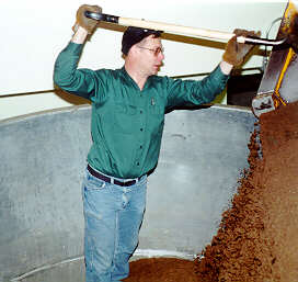
 Once
the sand is in the tank, it must be shoveled and flattened down as much
as possible. This is done by rolling it as so:
Once
the sand is in the tank, it must be shoveled and flattened down as much
as possible. This is done by rolling it as so: 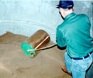
 This
is a picture of the sparge and it shows what the screen at the bottom looks
like. This is made of 1/2" pvc and the bottom 6" are screen,
as displayed in the picture. A hole is dug with a posthole digger
and then the sparge is placed in the hole and then backfill as depicted
here:
This
is a picture of the sparge and it shows what the screen at the bottom looks
like. This is made of 1/2" pvc and the bottom 6" are screen,
as displayed in the picture. A hole is dug with a posthole digger
and then the sparge is placed in the hole and then backfill as depicted
here: 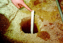
 The
photo to the left has students taking a level measurement for the experiment. The
photo on the right has students taking another measurement from the sitegage
on the side of the tank.
The
photo to the left has students taking a level measurement for the experiment. The
photo on the right has students taking another measurement from the sitegage
on the side of the tank. 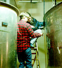
 This
picture exhibits the completed sparge along with the air coming from the
blower. Inverted buckets are used to measure the air flux rates
from various distances from the sparge. This experiment only utilized
the subsurface remediation tank, but this circular 'well' can be placed
inside the mesoscale subsurface remediation vessel to study the effects
of having a well in a square area.
This
picture exhibits the completed sparge along with the air coming from the
blower. Inverted buckets are used to measure the air flux rates
from various distances from the sparge. This experiment only utilized
the subsurface remediation tank, but this circular 'well' can be placed
inside the mesoscale subsurface remediation vessel to study the effects
of having a well in a square area.
You are number  to visit this page since April 19, 1997.